
A Guide to National Electrical Code (NEC) Grounding and Bonding Requirements for Rigid Metal Conduit
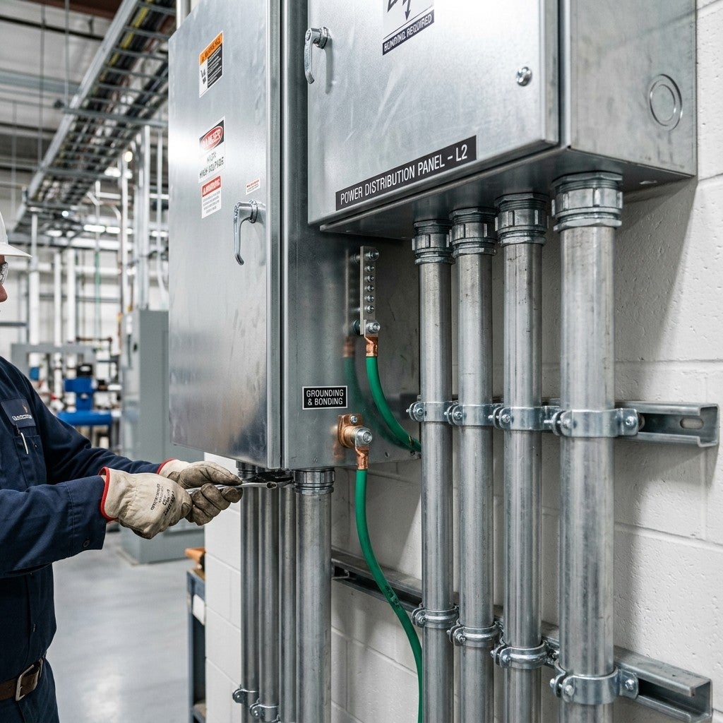
Rigid Metal Conduit (RMC) grounding and bonding requirements are governed primarily by NFPA 70® National Electrical Code®, Article 250, which permits properly installed RMC to serve as an Equipment Grounding Conductor (EGC) under NEC 250.118(2). Compliance with these requirements — from continuity of the conduit system to correct bonding at service equipment — determines whether the installation will safely clear ground faults, pass inspection, and protect personnel and property from electrical hazards.
Why Grounding and Bonding Matter for RMC Systems
Grounding and bonding are not administrative obligations — they are the mechanism by which an electrical system clears faults before those faults cause fires or electrocution. For RMC installations specifically, the conduit itself functions as both a physical wiring enclosure and, when properly installed, the return path for ground-fault current.
When a line-to-ground fault occurs — a phase conductor contacting the metal conduit, for example — fault current must travel back to the electrical source through a low-impedance path that is reliable enough to trip the overcurrent protective device (OCPD) quickly. An inadequate or interrupted EGC path means the OCPD may not operate, leaving energized metal enclosures that pose an electrocution and fire risk.
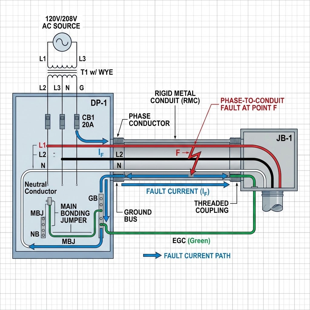
Three distinct consequences follow from non-compliant grounding and bonding:
- Safety: Energized enclosures endanger workers, occupants, and first responders.
- Code compliance: Deficient bonding is a frequently cited NEC violation at service inspections.
- System performance: High-impedance fault paths cause nuisance tripping, equipment damage from sustained fault current, and arc flash hazards.
RMC’s steel construction — hot-dip galvanized inside and out — gives RMC inherently low impedance characteristics that make it well-suited for EGC duty. But that physical capability means nothing unless every coupling, fitting, and termination maintains mechanical and electrical continuity.
NEC Definitions
Applying Article 250 correctly to RMC starts with understanding what the code means by its core terms. The definitions below are drawn from NEC Article 100 and are the foundation for every code citation that follows.
Equipment Grounding Conductor (EGC)
The conductive path(s) that provide a ground-fault current path and connects normally non-current-carrying metal parts of equipment together and to the system grounded conductor, the grounding electrode conductor, or both. An EGC can be a wire, a metal raceway, or other listed means — including RMC under NEC 250.118(2).
Grounding Electrode System (GES)
The network of grounding electrodes — ground rods, concrete-encased electrodes, metal underground water pipes, and other listed electrodes — that are bonded together to form a unified connection between the electrical system and the earth. The GES provides a reference voltage and dissipates transient overvoltages; it is not a reliable fault-clearing path for ground faults.
Bonding and Bonding Jumpers
Bonding is the permanent joining of metallic parts to form an electrically conductive path that ensures electrical continuity and the capacity to safely conduct any fault current imposed.
- Equipment Bonding Jumper: A connection ensuring continuity between two or more portions of the EGC.
- Main Bonding Jumper (MBJ): The connection at the service equipment between the grounded conductor (neutral) and the equipment grounding conductor bus. The MBJ creates the fault-clearing loop at the service.
- System Bonding Jumper (SBJ): Performs the same function as the MBJ but at a separately derived system (e.g., a transformer secondary).
Ground Fault Current Path
An electrically conductive path from the point of a ground fault on a wiring system through normally non-current-carrying conductors, equipment, or the earth to the electrical supply source.
Effective Ground Fault Current Path (NEC Article 100)
An intentionally constructed, permanent, low-impedance electrically conductive path designed and intended to carry fault current from the point of a ground fault on a wiring system to the electrical supply source, and that facilitates the operation of the circuit overcurrent protective device or the ground fault detectors on high-impedance grounded systems. The earth is explicitly excluded from being considered an effective ground fault current path.
This definition is the controlling standard against which all RMC installations must be measured. The path must be low impedance (to generate sufficient fault current), permanent (not subject to loosening), and intentional (not accidental metal-to-metal contact).
RMC as an Equipment Grounding Conductor
Permission and Conditions Under NEC 250.118(2)
NEC 250.118 lists the types of wiring methods and conductors that qualify as EGCs. Under NEC 250.118(2), RMC is explicitly recognized as a permitted EGC when it is installed in accordance with Article 344.
This recognition carries significant practical value. When RMC meets the installation conditions, no separate EGC wire is required inside the conduit — the conduit itself serves that function. RMC provides a recognized low-impedance fault-current path when properly installed.
Continuity Requirements
For RMC to qualify as an EGC, every section of the conduit run must satisfy three conditions:
- Secure support: RMC must be secured in accordance with NEC 344.30 — within 900 mm (3 ft) of each outlet box, junction box, device box, cabinet, conduit body, or other conduit termination, and at intervals not exceeding 3 m (10 ft). Improper support may contribute to mechanical damage or loose fittings, which can compromise continuity, but 344.30 itself is primarily a support rule.
- Mechanical continuity: Every coupling and fitting must be made up wrench-tight. A finger-tight coupling presents a high-resistance joint that can prevent adequate fault current flow. NEC 344.42 requires fittings to be made up tight — a requirement that directly supports EGC function.
- Listed fittings: Use fittings that are identified/listed for the wiring method and application and installed per listing and manufacturer instructions.
Fittings That Maintain EGC Continuity
The following fitting types, when properly installed and torqued, maintain EGC continuity for RMC:
- Threaded couplings and locknuts — The standard threaded connection provides metal-to-metal contact across the joint when installed wrench-tight.
- Threadless couplings (listed type) — Used for cut conduit ends; must be listed and installed per manufacturer instructions.
- Bonding bushings (NEC 250.92, 250.96) — Bonding bushings are commonly used where supplemental bonding is required, including many service-equipment and knockout-related applications.
Fittings That Can Interrupt EGC Continuity
- Non-listed connectors — No assurance of adequate contact area or clamping force.
- Standard locknuts alone at services — Standard locknuts alone are generally not accepted as the sole bonding means for service raceways; use one of the bonding methods recognized by NEC 250.92(B).
- Expansion fittings without integral or supplemental bonding jumpers — Expansion fittings, by design, allow axial movement that breaks metal-to-metal contact.
- Improperly made-up threadless connectors — A connector set screw that is not torqued to the manufacturer’s specification creates a high-resistance joint.
Key NEC Articles for RMC Grounding and Bonding
RMC grounding and bonding requirements span two primary articles — Article 250 (Grounding and Bonding) and Article 344 (Rigid Metal Conduit) — with additional requirements for specific conditions in Articles 300, 501 through 503, and 680. The sections below address the provisions most directly relevant to RMC EGC performance.
Article 250 — Grounding and Bonding
Article 250 is the primary authority for grounding and bonding in electrical installations. The following Parts and sections apply directly to RMC installations.
NEC 250.4 — General Requirements for Grounding and Bonding
NEC 250.4 establishes the performance goals that all grounding and bonding methods must achieve. For grounded systems, the five requirements are:
- Electrical systems shall be connected to earth in a manner that limits the voltage imposed by lightning, line surges, or unintentional contact with higher-voltage lines.
- The electrical system shall be grounded so that fault current facilitates OCPD operation.
- Normally non-current-carrying conductive materials enclosing electrical conductors shall be connected together and to the electrical supply source in a manner that establishes an effective ground-fault current path.
- Normally non-current-carrying conductive materials shall be connected together and to the electrical supply source so that the maximum voltage to ground on these materials is limited.
- Earth shall not be used as the sole equipment grounding conductor or effective ground-fault current path.
Item 5 is the explicit statutory basis for rejecting earth-only grounding schemes. For RMC, this means the conduit system must form a continuous metallic path from the fault point back to the source — earth contact alone does not satisfy the requirement.
NEC 250.86 — Other Conductor Enclosures and Raceways
NEC 250.86 requires that all metal enclosures and raceways — other than those enclosing service conductors — be connected to the EGC. RMC used for feeders and branch circuits falls under this requirement. The conduit run must be electrically continuous and effectively bonded to the equipment and enclosures it serves so that it forms an effective ground-fault current path.
NEC 250.92 — Services — Bonding Requirements
NEC 250.92 mandates bonding of all metalwork associated with service-entrance conductors. The bonding requirement at services is more stringent than at feeders because the overcurrent protection upstream of the service equipment is the utility’s, which may not operate quickly enough to clear a fault through a high-impedance path. Section 250.92(B) lists the methods permitted for service bonding — covered in detail in the Bonding at Service Equipment section below.
NEC 250.96 & NEC 250.97 — Bonding Other Enclosures
NEC 250.96(A) requires bonding for metal parts of the electrical installation to ensure the effective ground-fault current path. NEC 250.97 specifically addresses concentric and eccentric knockouts: where oversized knockouts reduce the cross-sectional area available for fault current, supplemental bonding may be required depending on the circuit voltage to ground, the enclosure connection, and whether an approved bonding means is already provided.
NEC 250.102 — Bonding Conductors and Jumpers
NEC 250.102 governs sizing and installation of bonding jumpers. Supply-side bonding jumpers (those on the line side of service equipment) are sized from NEC Table 250.102(C)(1) based on the area of the largest ungrounded service conductor. Load-side bonding jumpers are sized no smaller than required by NEC Table 250.122.
NEC 250.118 — Types of EGC (Focus on RMC)
As noted above, NEC 250.118(2) permits RMC to serve as an EGC when the raceway system is electrically continuous and installed in compliance with applicable NEC requirements. NEC 250.118 also permits combinations — for example, a copper EGC run inside RMC provides a redundant fault path. Although not generally required by the NEC, engineers specifying critical systems in industrial, healthcare, or data center applications sometimes require a separate EGC wire inside RMC despite the conduit’s own EGC qualification.
NEC 250.122 — Sizing the EGC
When a separate EGC is run inside RMC, its minimum size is determined from NEC Table 250.122, based on the rating or setting of the OCPD protecting the circuit. If ungrounded conductors are upsized to account for voltage drop, the EGC must be proportionally upsized per NEC 250.122(B).
Article 344 — Rigid Metal Conduit: Installation
Article 344 governs the physical installation of RMC. Sections relevant to EGC performance include:
- 20: Trade size designations and wall thickness compliance — dimensional consistency is required for threaded joints to achieve full metal-to-metal contact.
- 28: Reaming and threading — cut conduit ends must be reamed to remove burrs. Burrs reduce the contact area at fittings and can also damage wire insulation, which is relevant if a separate EGC wire is pulled.
- 42: Couplings and connectors must be made up wrench-tight.
- 46: Conduit terminations must be provided with bushings or other identified means of protecting conductors from abrasion as required by 344.46 and applicable provisions of 300.4(G).
- 30: Support requirements (spacing per NEC Table 344.30(B)(2)) must be maintained to prevent conduit separation.
Bonding at Service Equipment
The bonding requirements at service equipment are fundamentally different from those that govern feeders and branch circuits. That difference is driven by the fault-clearing environment unique to the service point — and failing to meet the higher service standard is one of the most common and consequential NEC violations in field installations.
Why Standard Locknuts Are Not Sufficient
At service equipment, the bonding standard is higher than at feeders and branch circuits downstream. The reason is straightforward: the overcurrent protection upstream of the service disconnect belongs to the utility, and utility fuses or relays are not calibrated to interrupt a fault through a high-impedance path in a customer’s wiring system. The only reliable fault-clearing mechanism at a service is to keep impedance so low that a fault drives massive current, ensuring that the service disconnect or its integral protection operates instantly.
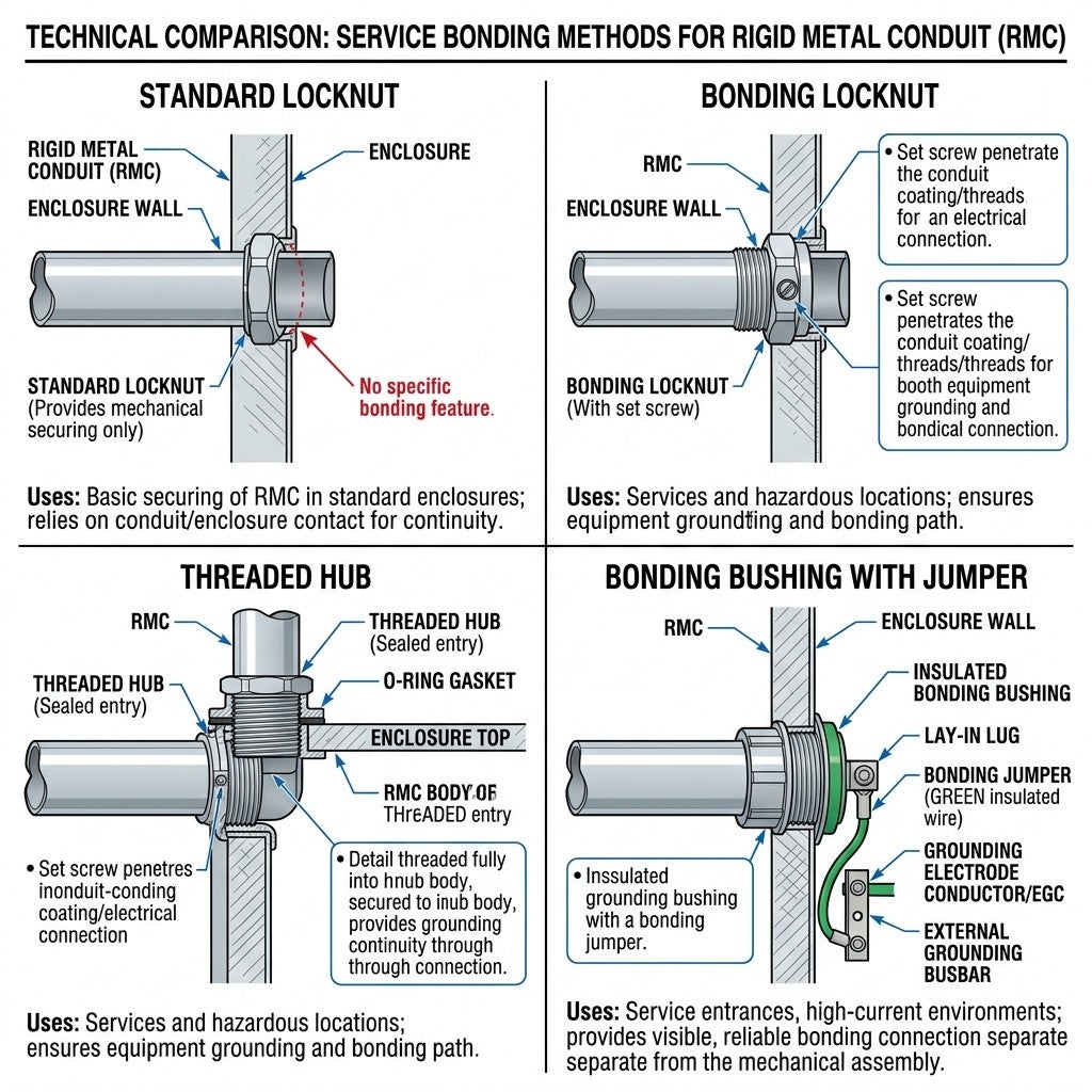
Standard locknuts create a sharp-ring contact with the enclosure that is not sufficient to ensure low-impedance bonding under fault conditions. NEC 250.92(B) therefore prohibits reliance on standard locknuts alone as the sole bonding method at service equipment.
Permitted Bonding Methods — NEC 250.92(B)
NEC 250.92(B) permits the following methods for bonding service equipment, individually or in combination:
- Threaded connections or threaded couplings: Where RMC is threaded directly into a threaded hub on a service enclosure, the threaded engagement constitutes an acceptable bond.
- Threadless couplings and connectors listed for grounding: Specifically listed for this service; the listing designation confirms the contact is sufficient for bonding.
- Bonding jumpers sized per NEC 250.102: An equipment bonding jumper connecting the RMC or its fitting to the service enclosure. This is the most commonly used method where a bonding bushing is installed at the conduit end, and a bonding conductor runs from the bushing lug to the neutral/ground bar.
- Other devices listed for bonding: This includes bonding locknuts (which are distinct from standard locknuts — bonding locknuts have serrated or sharp teeth that bite through paint and oxide layers to ensure a reliable connection).
Bonding Bushing Selection
A bonding bushing consists of a threaded bushing body with an integral or attached bonding lug. The bushing is installed at the conduit end inside the enclosure, replacing or supplementing the standard locknut. A bonding jumper is then connected from the lug to the neutral bar or the ground bus. Bonding bushings must be listed for the application and are available in sizes to match the full range of RMC trade sizes from 1/2 in. through 6 in.
Sizing the Equipment Grounding Conductor
When RMC serves as the sole EGC, sizing is implicit in the conduit trade size — the conduit is the conductor. When a separate wire EGC is installed inside RMC, NEC 250.122 governs its minimum size. The two scenarios interact in ways that require careful attention during design and inspection.
Using NEC Table 250.122
When a separate copper or aluminum EGC is run inside RMC — either by specification or by choice — its minimum cross-sectional area is set by NEC Table 250.122. The table input is the rating of the OCPD protecting the circuit:
| OCPD Rating (A) | Minimum Copper EGC Size |
|---|---|
| 20 | 12 AWG |
| 60 | 10 AWG |
| 100 | 8 AWG |
| 200 | 6 AWG |
| 300 | 4 AWG |
| 400 | 3 AWG |
| 600 | 1 AWG |
| 800 | 1/0 AWG |
| 1,000 | 2/0 AWG |
| 1,200 | 3/0 AWG |
*Partial excerpt from NEC Table 250.122. Consult the current NEC for the complete table.*
Proportional Upsizing — NEC 250.122(B)
Where ungrounded phase conductors are upsized beyond the minimum required size — typically to compensate for voltage drop over long runs — the EGC must be increased proportionally. The calculation:
Upsized EGC area = (Installed conductor area ÷ Required conductor area) × Table 250.122 EGC area
Failure to upsize the EGC when conductors are increased is a common inspection finding. The logic is sound: a larger conductor has lower impedance, which means fault current will be higher, and the EGC must be capable of carrying that current without failing before the OCPD operates.
Parallel Conductors — NEC 250.122(F)
Where a feeder is run in two or more parallel conduits, a full-sized EGC — as determined by NEC Table 250.122 — is required in each conduit. It is not permissible to run a single EGC in one of the parallel conduits and rely on RMC continuity in the others.
RMC’s Own EGC Role and Separate Wire Interaction
When RMC serves as the EGC by itself, no separate wire is required by code. When both RMC and a wire EGC are present in the same conduit, both qualify as EGCs per NEC 250.118. The presence of a wire EGC does not diminish or override the conduit’s EGC status, but the wire must still be sized per NEC Table 250.122. The two paths operate in parallel, reducing overall impedance — a benefit in fault-clearing performance.
Common Installation Errors and Inspection Pitfalls
The sections below document recurring deficiencies identified during NEC inspections of RMC grounding and bonding installations. Each item connects the field failure to its specific code requirement so that corrective action is unambiguous.
Broken Conduit Runs Without Bonding Jumpers
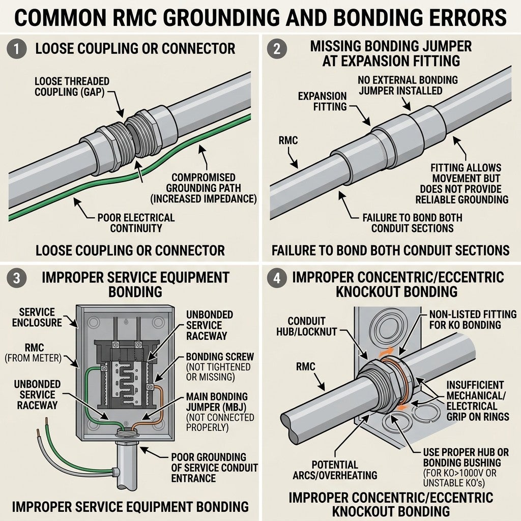
Any interruption in the metallic continuity of the conduit system creates a gap in the EGC path. Common sources of interrupted runs include:
- Conduit entering a pull box through a non-metallic bushing without a separate EGC connection
- Flexible metal conduit (FMC) or liquidtight flexible metal conduit (LFMC) used as a transition without a bonding jumper — lengths exceeding 1.8 m (6 ft) require a separate EGC regardless of flexible conduit type per NEC 250.118(5)(c) and 250.118(6)(c)
- Conduit transitions to a different raceway type without an EGC wire bridging the transition
Non-Listed Fittings
Listed fittings undergo testing for contact resistance and mechanical retention under fault-current conditions. Non-listed fittings may appear visually identical but lack the assurance of adequate performance. Using a non-listed fitting invalidates the conduit’s EGC qualification for that section of the run, and an AHJ (Authority Having Jurisdiction) can require replacement.
Improper Service Bonding — Relying Solely on Standard Locknuts
This is among the most frequently cited service installation deficiencies. The field installation sequence — install conduit, run locknut, tighten — produces a mechanically secure assembly. However, NEC 250.92(B) requires bonding, not just mechanical retention. Where inspectors identify conduit at service equipment held only by standard locknuts, supplemental bonding jumpers or bonding bushings may need to be installed before the installation will pass.
Concentric and Eccentric Knockouts — NEC 250.97
Concentric and eccentric knockouts reduce the metal contact area between the conduit fitting and the enclosure wall. NEC 250.97 addresses bonding around concentric and eccentric knockouts in certain installations, particularly where the connection could impair the effective ground-fault current path. These conditions are especially important in higher-voltage-to-ground installations, where preserving an effective ground-fault current path is critical.
Expansion Fittings Without Bonding Jumpers
Expansion fittings accommodate thermal expansion and contraction in long conduit runs — typically required where conduit runs exceed approximately 30 m (100 ft) exposed to temperature variation. The sliding joint in an expansion fitting breaks metal-to-metal contact by design. Inspectors frequently find these jumpers missing on rooftop conduit runs and in locations where conduit transitions between heated and unheated spaces.
Lack of Bushing at Conduit Terminations
NEC 344.46 requires a bushing (or equivalent protection) at the end of conduit entering a box or enclosure to protect conductors from sharp threads. Beyond conductor protection, the choice of bushing matters for bonding: where bonding is required, the bushing must be a bonding type with a lug.
Special Situations
Standard RMC grounding and bonding requirements apply in most commercial and industrial installations. The following situations impose additional or modified requirements that engineers, contractors, and inspectors must recognize early in the design and review process.
Hazardous Locations — Articles 501 Through 503
Hazardous locations impose additional wiring-method and bonding considerations under Articles 501 through 503. Because requirements vary by classification, equipment type, and installation method, the applicable article and equipment listing should be reviewed directly for project-specific bonding requirements. RMC is one of the preferred wiring methods in Class I, Division 1 locations per NEC 501.10(A) due to its mechanical strength and ability to contain and cool arc products that might otherwise ignite external atmospheres. That advantage is nullified if the bonding system fails to clear a fault promptly.
Seismic Zones and Flexible Conduit Sections
In seismic design categories C through F (per ASCE 7 and local building codes), conduit systems must accommodate differential movement between structures. Flexible conduit sections — either FMC or LFMC — are installed at seismic joints and equipment connections. As noted above, these flexible sections require separate EGC wires when their length exceeds 1.8 m (6 ft), and the EGC must be sized per NEC Table 250.122. Engineers designing conduit layouts in seismic zones must account for EGC continuity at each flexible section in the routing.
Wet and Damp Locations — Corrosion and Bonding Reliability
In wet or corrosive locations, galvanic corrosion at conduit joints can increase junction resistance over time, degrading the EGC performance of the conduit run. NEC 344.10 permits RMC use in concrete, direct earth contact, and corrosive environments, but NEC 300.6 requires that the installed material be suitable for the corrosive condition or be protected by a suitable coating.
Where corrosion risk exists, field practices that support long-term EGC reliability include:
- Using corrosion-resistant (PVC-coated) RMC per ANSI/NEMA RN 1 in buried or embedded applications
- Applying conductive joint compound at threaded connections in wet locations to maintain electrical contact despite oxide layer formation
- Running a separate EGC wire inside the conduit as insurance against junction resistance degradation over the life of the installation
- Specifying stainless steel or silicon bronze hardware for fittings in marine or chemical process environments
Inspection and Testing Checklist
The following checklist supports pre-inspection self-review by the installing contractor and field verification by the AHJ. Each item maps directly to a specific NEC requirement. Work through the list in sequence from the service point outward to ensure no section of the system is skipped.
- Confirm RMC is listed and marked per UL 6 and that the material certification documents are available for review.
- Verify mechanical continuity along the entire conduit run: all couplings made up wrench-tight, no visible gaps between conduit sections.
- Check support spacing per NEC Table 344.30(B)(2): maximum 3 m (10 ft) between supports, and within 900 mm (3 ft) of each enclosure termination.
- Inspect conduit terminations at each box and enclosure: confirm listed bushings or connectors are installed per NEC 344.46.
- Verify service bonding method per NEC 250.92(B): confirm that bonding bushings, bonding locknuts, or threaded hubs — not standard locknuts alone — are used at service equipment.
- Confirm bonding jumper sizing at service per NEC Table 250.102(C)(1): measure conductor size and compare against the largest ungrounded service conductor.
- Identify expansion fittings in the conduit run and verify if a bonding jumper should be installed.
- Inspect concentric/eccentric knockout locations per NEC 250.97: verify that bonding is provided where required by the installation conditions and connection method.
- Verify EGC wire sizing where a separate EGC is installed inside RMC: confirm size against NEC Table 250.122 based on the OCPD rating.
- Check proportional EGC upsizing per NEC 250.122(B): where phase conductors are oversized for voltage drop, confirm the EGC circular mil area is proportionally increased.
- Inspect parallel feeder conduits per NEC 250.122(F): confirm a full-sized EGC is present in every parallel conduit, not just one.
- Review flexible conduit transitions: confirm lengths exceeding 1.8 m (6 ft) have a separate EGC wire, sized per NEC Table 250.122.
- Inspect hazardous location bonding (where applicable) per NEC 501.30: verify that all bonding and raceway connection methods in the classified area comply with the applicable hazardous-location article and the equipment listing.
- Confirm ground continuity by testing: use a low-resistance ohmmeter or ground impedance tester at the far end of each feeder run to verify conduit continuity from the equipment grounding/bonding termination point at the source equipment to the remote enclosure. Verify continuity and low-impedance performance using approved test methods and compare results to project requirements, manufacturer guidance, and AHJ expectations.
- Verify grounding electrode system connections per NEC Article 250 Part III: confirm the grounding electrode conductor is terminated at the service equipment in accordance with NEC Article 250 and bonded to the grounded service conductor by the required bonding means.
Summary and Key Takeaways
Rigid Metal Conduit is one of the most capable wiring methods available for grounding and bonding — but that capability depends entirely on installation quality. NEC 250.118(2) permits RMC to serve as the EGC for circuits, eliminating the need for a separate grounding wire when the conduit run is mechanically and electrically continuous. That condition is non-negotiable: a single improperly made-up coupling, a missing bonding bushing at the service enclosure, or an unbridged expansion fitting can raise the fault path impedance high enough to prevent OCPD operation.
The five principles that govern compliant RMC grounding and bonding:
- Every fitting and connection must be properly made up and identified for the wiring method and application — the conduit’s EGC qualification depends on continuous, low-impedance joints.
- Service bonding is a separate and higher standard — standard locknuts alone are not sufficient at service equipment; service raceways must be bonded using a method recognized by NEC 250.92(B), such as threaded hubs, bonding-type fittings, bonding bushings with jumpers, or other listed bonding means.
- Expansion fittings require bonding jumpers — by design, they break metal-to-metal contact; by code, that break must be bridged.
- Concentric and eccentric knockouts may require supplemental bonding — reduced contact area means the metal path cannot be relied upon without additional bonding under NEC 250.97.
- Separate EGC wires, when present, must be sized correctly and run in every parallel conduit — the conduit’s EGC role does not relieve the designer or installer from applying NEC Table 250.122 and 250.122(F) correctly.
For electrical engineers specifying RMC systems, licensed electricians installing them, and inspectors reviewing the work, the starting point is always the same: verify that the effective ground-fault current path — as defined in NEC Article 100 — is intentional, low-impedance, and permanent from every point in the system back to the source. When RMC is properly installed, it delivers that path reliably, project after project.
Wheatland Tube
*References: References are based on the current edition of NFPA 70 (NEC). Local jurisdictions may adopt earlier editions and may amend specific provisions. All section and table references in this guide apply to the current adopted edition of the NEC; verify the edition adopted by the AHJ for the project location, as local amendments may apply.*